 Contact
ECE 6390 Project
KungFu Project: W/V Band Satellite Design
Communication Experiment Design
The WAVE Coverage
The large bandwidth availability in W-band will allow the development and distribution of new broadband services on a large scale with high quality of service levels. The W-band payload will provide three coverage beams, as shown in Fig. 1.
Figure -1 WAVE Coverage.
Beam A with a diameter of about 2000 km, is expected to cover a wide area of United States, in order to perform the propagation experiment measurements. An on board generated beacon signal will be transmitted towards different locations or sites within beam A coverage area to be analyzed at the receiving stations. Beam B is expected to have a diameter of about 700 km covering most of Texas. The third beam, named C, is expected to have a diameter of about 200 km around the Amarillo fixed station in order to carry out the experimental characterization of the W-band channel and the various experiments for data relay services between beams B and C. Two different types of stations are proposed: a fixed station located at Amarillo site and a transportable station, as shown in Fig. 2. The transportable station will offer the advantage of performing different measurements at different locations or sites. The implementation of the transportable station increases the complexity of the payload (antennas and other technological aspects related to HPA, LNA, etc.), but at the same time permits a particularly large collection of propagation measurements in various places and weather conditions. Furthermore, it could provide the basis for studies concerning future development of services in mobility, the definition of proper transmission strategies for high-rate communications and the design of suitable reconfigurable transceivers for reliable beam switching. The 81-86 GHz and 71-76 GHz will be the frequency ranges for uplink and downlink, respectively.

Link Budget
A combination method that reflects the interdependence of the various attenuation factors better considers some of the propagation effects uncorrelated. The corresponding ITU-R recommendation adopts the following formula:
![]()
The majority of the atmospheric phenomena exhibits a stochastic behavior both in time and space , therefore, differ from all other deterministic factors (e.g., free space loss) that affect the satellite link under clear sky link conditions. Since propagation impairments have a significant impact only for less than one percent of the time during a year, the system gain must be enhanced through an additional fade margin carefully estimated to satisfy the desired availability.

Table 1. Summary of the Earth-GEO link data rate
Modulation

Figure 3. Block diagram of the W-band satellite modem chain
The transmitted 16-QAM signal can be expressed by the following formula:
![]()
where each transmitted 4-bit symbol is mapped into 16 possible complex levels. M-ary QAM modulations don’t present any residual carrier component in their spectrum. So the carrier recovery should be recovered by means of suitable circuits. Note that symbols belonging to a squared 16-QAM constellation lie on three concentric circles (see Figure 4).
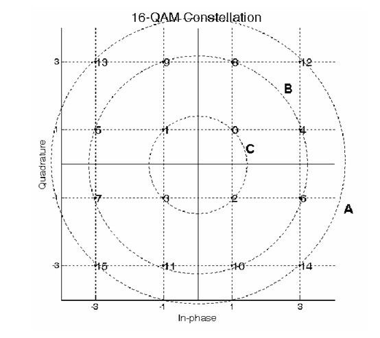
Figure 4. Squared 16-QAM constellation
Acquisition of Measurements
The receiving stations must be capable of measuring both the power of the sinusoidal signals and the bit error rate (BER) in order to evaluate the quality of the transmission. To measure the power of the sinusoidal signals, the satellite must send a stable enough beacon signal. With the proposed configuration, it is appropriate to use also radiometric equipment, operating at lower frequencies - typically in Ka band - in order to perform the so-called "bias removal", specifically to estimate the "zero dB" attenuation level. This measurement technique allows the calibration of the channel power, considering the clear-air attenuation due to presence of gases in atmosphere, which also affects the signal transmitted by beacon.
The BER measurement must take place, in presence of a modulated signal that will allow evaluating the effect of the tropospheric path length on the transmitted signal if carried out in different locations at different elevation angles. Also in this case evaluations carried out during phases A and B of DAVID project are taken into account. The combined measurement of the power level and BER allows separation of two effects that arise together, namely the additional attenuation (due to rain, clouds, etc...) and the noise (caused by the electronic components at both ends).
The Payload
The WAVE payload is composed of two types of transponders, according to the mission definition and requirements: a transparent and a regenerative one. The first is designed to perform the telecommunication experiment and the second is used to carry out the channel characterization. The transparent transponder will work on a variety of selectable channel bands used for transmission on beams B and C to carry out the channel experiments for variable-capacity data relay services and different signal patterns. The propagation experiment will be carried out through beam A, where a W-band beacon will be used for downlink channel characterization. The regenerative transponder will provide the propagation experiments for uplink channel through the beams B and C; moreover, it will carry out a characterization of the channel Bit Error Rate (BER). This is done through an on board processing of the uplink-transmitted signals; the measurements are then sent back to Earth using the beacon.
A simple scheme of the WAVE payload, that includes redundancies, is shown in Fig. 5. At the reception section, the front-end should be implemented in an integrated antenna system, to achieve compliance with high requirements of G/T and to reduce the high wave-guide losses in W-band. The transmission front-end is based on HPA technology to accomplish the high power requirements that could not be achieved using solid-state devices.

Figure 5-Basic Architecture of the WAVE Payload
From the preliminary analysis of the RF payload performances, it results that the compliance with EIRP requirements can be obtained using a 25 W HPA. The WAVE payload will be placed on board a host platform dedicated to other mission into a GEO orbit so the mass, size, and power requirements are reduced to achieve this goal. From the first analysis, the maximum expected DC power requirements is 300 W and the mass is about 30 kg. The characterization of the uplink channel will be performed sending known sequences through the uplink channel; then the uplink signals is captured through a coupler and demodulated with a variable data rate (2-10 Mbps). The BER is then calculated by comparing the sequences with a standard sequence stored on board and the measurements are thereafter retransmitted to Earth using the beacon (Beam A). The required specifications of the antennas are shown in Table 2.
Table 2 - Specifications of the antennas
| Coverage | Spot |
Wide(Texas) |
United States |
Beam Width |
200 km |
700 km |
2000 km |
Beam Width from |
0.3 ° x 0.3° |
0.68° x 1.05° |
1.64° x 3.00° |
Area |
0.07° (0.043°) |
0.56° |
3.86° |
Receiving Band |
81-86 GHz |
81-86 GHz |
N. A. |
Transmitting Band |
71-76 GHz |
71-76 GHz |
71-76 GHz |
Rx Gain |
> 52.9 dBi |
> 43.1 dBi |
N. A. |
Tx Gain |
> 51.9 dBi |
> 42.1 dBi |
> 33 dBi |
The on board section allows a large flexibility of configuration; the idea is to identify a hardware platform where it is possible to program various types of processing architectures. It is possible to assume modulation techniques that have great robustness, rather than spectral efficiency, to obtain a good channel characterization. For the propagation experiment, the data should be uncoded to verify channel performances but at the same time permits to add different coding schemes to study the reaction to errors produced by the W-band satellite channel.